Currently in Development
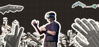
I am currently working on a humanoid robot arm project with the University of Waterloo’s design teams, WATonomous and UW Reality Labs. The goal is to create an anthropomorphic humanoid robot arm that can perform a variety of tasks with dexterity and precision.
The CURRENT focus is on creating a V1 prototype with full hardware. This includes the mechanical design, power electronics, embedded software, and control algorithms. The V1 prototype will be capable of teleoperated control via Quest 3 Headsets’ hand tracking through a custom Unity application built by the UW Reality Labs team.
The ULTIMATE goal is to train the humanoid arm to perform tasks automatically using reinforcement learning. This will involve developing a robust simulation environment using NVIDIA’s Isaac Sim. The main objective is to get the humanoid arms to learn to autonomously type on a keyboard, which requires precise finger movements and coordination. (It would also look really cool since now LLMs can interact with my physical keyboard and edit code directly!)
My Role
I am a Co-op student for the WATonomous team during the Winter 2025 term, and I am responsible for several key aspects of the humanoid arm project:
Mounting a CANbus Transceiver in Docker
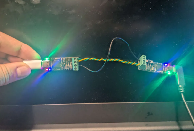
I am responsible for the interfacing between the hardware and software components of the humanoid arm. This includes developing the CAN bus communication protocols, integrating the sensors and actuators, and ensuring smooth data flow between the different systems. An interfacing ROS2 (Robot Operating System 2) C++ node is being developed to mount a USB2CAN transceiver to send and receive messages using a CANable 2.0 device.
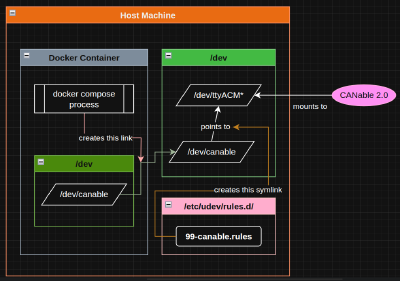
I am mounting the CANable 2.0 device in a Docker container to allow communication through ROS2 topics and services over a CAN bus. This setup requires configuration of the Docker container to recognize the CANable device, which is done by adding the device with a Linux symlink to the /dev/canable interface. The Dockerfile includes the necessary dependencies and configurations to ensure that the ROS2 node can communicate with the CAN bus effectively.
Read further below for more details on the interfacing system documentation.
Simulation and Data Visualization
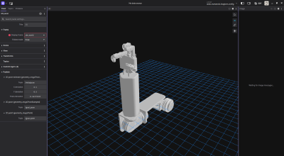
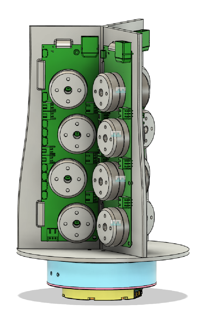
I am also working on the simulation URDF (Unified Robot Description Format) for the humanoid arm in NVIDIA’s Isaac Sim. This will allow us to test and refine the control algorithms in a virtual environment before deploying them on the physical robot. Within the URDF, I am also implementing the hardware IDs of all the motors and sensors, which is crucial for the CAN bus communication.
I first created a URDF file for the humanoid arm, which includes the kinematic and dynamic properties of the robot by using an open source Fusion360 script to export the model called fusion2urdf. This script generates a URDF file from the Fusion360 model, which can then be imported into Isaac Sim for simulation.
Here is my motion study of the humanoid arm to visualize the dynamics of the arm to gesture a thumbs up:
I also need to visualize the data from behaviour/control nodes to compare simulation results to real world movement. I am setting up Foxglove Studio to visualize the ROS2 topics and messages in real-time. This will help in debugging and analyzing the performance of the robot during teleoperation and autonomous tasks.
PCB Design and Assembly
Project Traincar: The PCB assembly for the hand controller board was done by hand, soldering 0.5mm pitch SMD components with a soldering iron and solder paste. This was a meticulous process that required precision and attention to detail to ensure that all components were correctly placed and soldered.
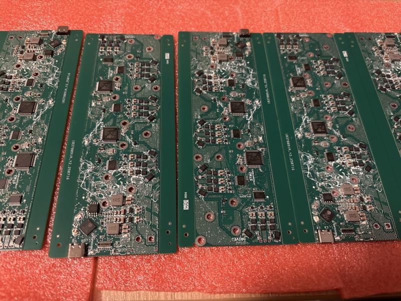
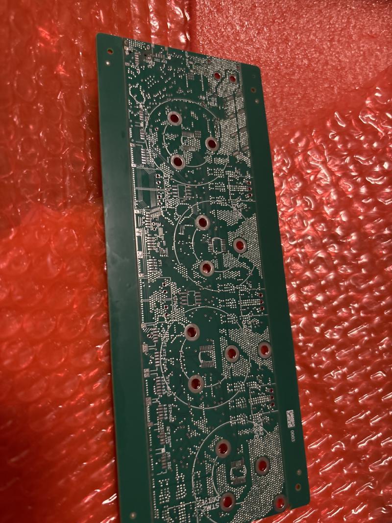
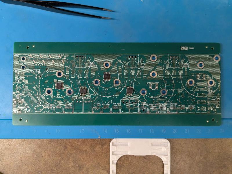

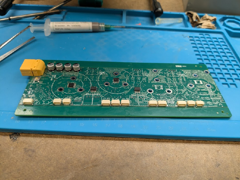
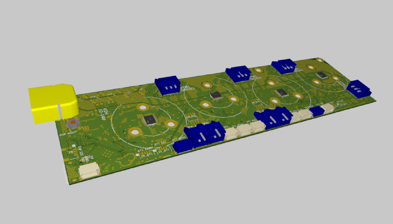
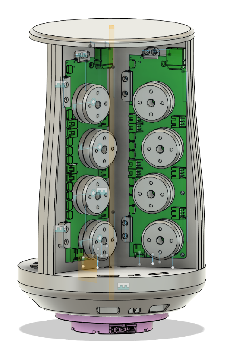
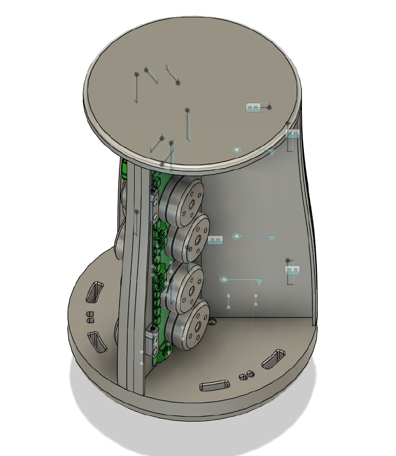
Each traincar PCB is responsible for controlling 4 motors in the hand, and there are 5 traincars in total for a full hand with 20 motors. The traincars communicate with a central controller board via a CAN bus, which allows for efficient and reliable communication between the different components of the hand.
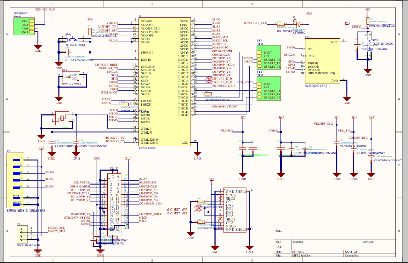
It contains an ESP32 based microcontroller, CAN transceiver, motor drivers, and power regulation circuitry. The PCB was designed to be compact and lightweight, while still providing all the necessary functionality for controlling the motors in the hand.
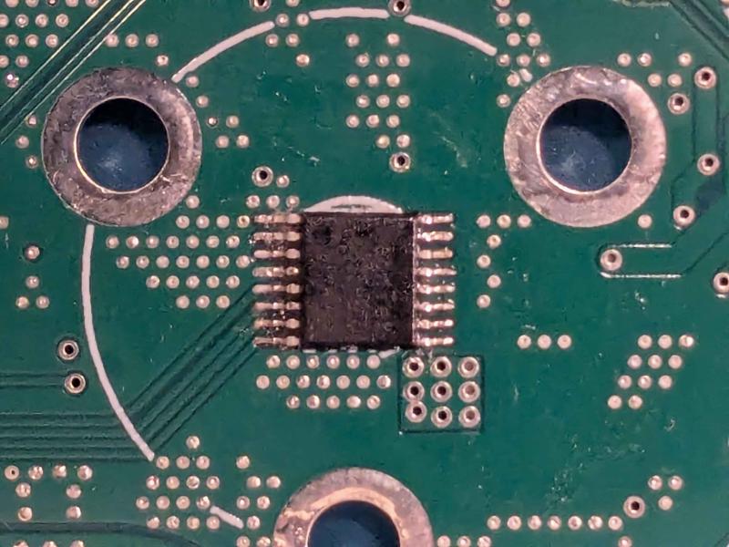
Some problems that were encountered during the assembly process included:
- Solder bridges between the fine pitch pins of the motor drivers
- Unprotected VIAs
Interfacing System Documentation
Below is my documentation for the interfacing system, which includes the CAN bus communication protocols, ROS2 package structure, and how to set up the CANable device in a Docker container.
Communication Protocols
- Intro to Communication Protocols (UWRT)
- Comparisons between protocols
CAN Package
Goal: Implement a ROS 2 package to bridge communication between a high-level controller and an embedded hand system via CAN bus. The package will:
- Receive ROS 2 movement messages from the controller/behaviour node.
- Convert and send these messages as CAN frames through a USB transceiver (accessible within a Docker container).
- Receive CAN frames from the embedded system containing hand odometry
- Convert and publish this odometry as ROS 2 messages for feedback to the controller.
- Location on the repository: humanoid/autonomy/interfacing/can
Persistent Device Mount for CANable USB Device in Docker
Ensure that the CANable USB device is always mounted to /dev/canable on the host system, making it easy to reference consistently in Docker containers.
The host system is responsible for setting up a symlink to /dev/canable , and the docker compose accesses the host’s symlink
How to setup the host system to mount the CANable 2.0 device to /dev/canable using symbolic links (symlinks)
- Purpose: ensure that the CANable device always mounts to the same port under
/dev/canable - Good to know terminology:
- Symlink: file that points to other files/directories on the machine
- udev - device manager for Linux kernel responsible for managing nodes in the
/devdirectory - The CAN transceivers all have serial numbers that are constant to the device
Find the /dev/ttyACMx port that the CANable 2.0 device mounts onto, where is a number
ls /dev/ttyACM*Find the serial number of the CANable device
udevadm info -a -n /dev/ttyACMx | grep -m 1 serialCreate a custom rule to make a persistent symlink, and ensure the correct serial value
echo 'SUBSYSTEM=="tty", ATTRS{idVendor}=="16d0", ATTRS{idProduct}=="117e", ATTRS{serial}=="208B38B43136", SYMLINK+="canable"' | sudo tee /etc/udev/rules.d/99-canable.rulesReload udev Rules and Trigger
sudo udevadm control --reload-rules
sudo udevadm trigger
Verify the new symlink
ls -l /dev/canableShould point to
/dev/tty/ACMx
- Purpose: ensure that the CANable device always mounts to the same port under
On startup, the interfacing docker container will always mount onto the host’s port called
/dev/canable/- file:
interfacing.DockerfileENV UDEV=1- required to pass the host machine’s udev symlinks to the container
- file:
docker-compose.interfacing.yamlprivileged: false- setting to true bypasses the symbolic link that the host set
devices: /dev/canable:/dev/canable- mount the host’s canable port to container’s canable port
network_mode: host- allow the container to access the host’s network interfaces
cap_add: NET_ADMIN- Grant capability to configure network interfaces
- file:
Initializing the CANable as a CAN Bus “Master” in Code
Set the CAN Bus speeds, message length, and queue length of CAN messages on the host’s CAN transceiver in a C++ ROS2 package in the “interfacing” directory in the autonomy
Setup CAN device parameters on can0 by running SLCAN Daemon
Run a bash script to call the slcand tool from can-utils to setup the bus speed, interface name, etc.
- “slcand : daemon for serial line CAN interface configuration”
- https://github.com/linux-can/can-utils?tab=readme-ov-file#serial-line-discipline-configuration-for-slcan-driver
- Daemon process that runs continuously in the background
- Handles both configuration and ongoing management
- Creates the interface and keeps it running
- This one command does everything
- The script for the can setup can be found in
can/scripts/setup_can.sh- Uses parameters from the
config/params.ymlto setup the CAN interface
- Uses parameters from the
How to change the CAN bus parameters/settings
autonomy/interfacing/can/config/params.yml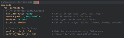
- After changing these values, you’d have to rebuild the container
./watod build
- After changing these values, you’d have to rebuild the container
ROS2 API
- Transmitting Data (ROS2 → CAN →Embedded)
- Role: ROS2-to-CAN Translator
- Process:
- Subscribes to a configurable list of ROS2 topics
- Receives any type of ROS2 message from these topics
- Transmits the CAN frames over the bus to embedded devices
- Converts/serializes the message data into CAN frames
- Format Agnostic
- doesn’t care about message structure, just forward raw ROS2 message data
- Receiving Data (Embedded → CAN → ROS2)
- Role: CAN-to-ROS2 Translator
- Process:
- Listen for incoming CAN messages from embedded devices
- Receives raw data packets from CAN bus
- Convert CAN frames back into ROS2 messages
- Publishes the data on appropriate ROS2 topics
Sending Messages from Subscribed Topics
Creating a test ROS2 publisher for sample finger xyz data
- changed topic name to
/test_controller
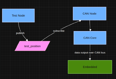
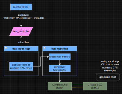
Preview
ROS2 Package Structure (Sending Messages)
CAN FD - Intro
- CAN FD uses the same differential pair structure of CAN 2.0, but with 2 different bit rates
- Arbitration Phase (slow)
- Who gets to talk
- Always slow (500kbps for compatibility)
- Contains: CAN ID, control bits, frame setup
- Data Phase (fast)
- The actual message
- Bitrate determined by BRS (bit rate speed) bit from the Arbritration Phase
- Contains: actual payload data + error checking
- Arbitration Phase (slow)
Classic CAN Frame:
Time:  0μs    10μs   20μs   30μs   40μs   50μs
       │      │      │      │      │      │
Volt: ─┐    ┌─┐    ┌─┐    ┌─┐    ┌─┐    ┌─
       └────┘ └────┘ └────┘ └────┘ └────┘
       Start  ID     RTR    Data   CRC    EOF

All bits: 2μs duration (500 kbps)
CAN FD Frame:
Time:  0μs    10μs   20μs   25μs   30μs   40μs
       │      │      │      │      │      │
Volt: ─┐    ┌─┐    ┌──┐┌┐┌┐┌─┐    ┌─────
       └────┘ └────┘  └┘└┘└┘ └────┘
       Start  ID     FDF  Fast Data  CRC
                     BRS  (0.5μs bits)

Arbitration: 2μs per bit (500 kbps)
Data phase:  0.5μs per bit (2 Mbps) ← 4x faster!